2.1 Basic Spacecraft Data
2.1.1 Spacecraft Reference Frames Definitions
2.1.1.1 Inertial Frame
The Orbital Elements are defined with respect to the inertial frame defined at 00:00 UT on 1. January 2021.
2.1.1.2 Local Orbital Reference Frame
• The origin of the Local Orbital Reference Frame (X, Y, Z) is the satellite in-flight centre of mass G.
• The unit vector Y is in the direction opposite to the Earth’s centre, the geocentric.
• The unit vector X is perpendicular to Y and parallel to the equator plane
• The unit vector Z is parallel with the Earth’s axis towards North.
2.1.1.3 Local Relative Orbital Reference Frame
The Local Relative Orbital Reference Frame (X1, Y1, Z1) has a similar definition as the Local Orbital Reference Frame except for local normal pointing, i.e. the unit vector Z1 is parallel to the local normal of the Earth’s Reference Ellipsoid, directed upward and crossing the spacecraft in-flight centre of mass G and the unit vector Y1 is in the plane containing the velocity vector in the Earth Fixed frame
This attitude is also known as Local Normal Pointing.
2.1.1.4 Body Reference Frame
After injection, for the modelling purpose it is assumed to occur in the equatorial plane, Perun 1p rotates freely, between 1 and 5 full rotations in a minute, standard assumption is 3. Rotation is determined by orientation of the Body Fixed Reference Frame (BFRF) with respect to the Local Orbital Reference Frame. General orientation of the BFRF with respect to the velocity vector is shown in Figure.

2.1.2 Perun 1p configuration
Platform Mass / kq 1.3
Payload Mass / kg 0.2
Total Dry Mass (with margin) / kg 1.1
Wet mass / kg 0.0
In fully deployed configuration the spacecraft is 0.1m high, solar array are not deployed.
The cross-sectional areas are 0.01m2 in all X, Y and Z directions.
In normal mode the spacecraft is not stabilized.
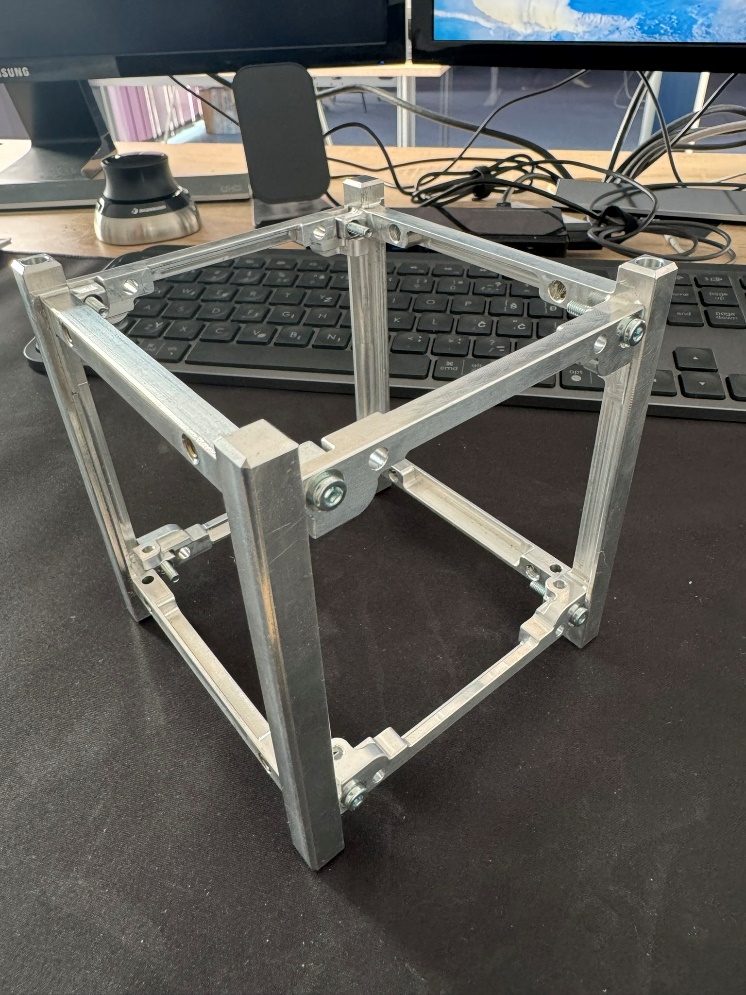
2.1.3 Structure
The Perun 1p platform utilises a quadratic shaped structure. The platform equipment and the payload Instrument Control units are mounted within the mechanical platform.
2.1.4 Propulsion Sub-system
Propulsion system is not envisaged for this CubeSat.
2.1.5 Electrical Power Sub-system
The Perun 1p EPS architecture consists of:
• Five –X, Y and Z facing solar panels using GaAs triple junction solar cells for power generation.
• Four Li-Ion batteries which will store un-used solar power during the Sunlit part of the orbit and return the power to the spacecraft during the eclipse periods
• A Power Conditioning and Distribution Unit (PCDU) which will regulate the solar power, manage battery charging, protect and distribute the main bus power, communicate with the on-board control and monitoring systems and activate deployment devices.